
Time-of-flight diffraction (TOFD) method of ultrasonic testing is a sensitive and accurate method for the nondestructive testing of welds for defects. TOFD originated from tip diffraction techniques which were first published by Silk and Liddington in 1975 which paved the way for TOFD.
TOFD as tip-diffraction techniques which utilized the principle that the tips of a crack when struck by a wave will diffract the signals back to the other location on the surface. The depth of these tips can be determined from the diffracted energy.
The use of TOFD enabled crack sizes to be measured more accurately, so that expensive components could be kept in operation as long as possible with minimal risk of failure.
Measuring the amplitude of reflected signal is a relatively unreliable method of sizing defects because the amplitude strongly depends on the orientation of the crack. Instead of amplitude, TOFD uses the time of flight of an ultrasonic pulse to determine the position of a reflector.
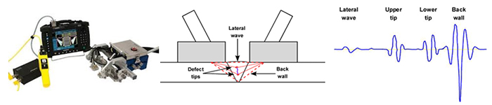
In a TOFD system, a pair of ultrasonic probes sits on opposite sides of a weld. One of the probes, the transmitter, emits an ultrasonic pulse that is picked up by the probe on the other side, the receiver. In undamaged pipes, the signals picked up by the receiver probe are from two waves: one that travels along the surface and one that reflects off the far wall. When a crack is present, there is a diffraction of the ultrasonic wave from the tip(s) of the crack. Using the measured time of flight of the pulse, the depth of a crack tip can be calculated automatically by simple trigonometry.
 |  |
Phased array ultrasonics (PAUT) is an advanced method of ultrasonic testing that has applications in medical imaging and industrial nondestructive testing. Common applications are to noninvasively examine the heart or to find flaws in manufactured materials such as welds.
Single-element (non-phased array) probes, known technically as monolithic probes, emit a beam in a fixed direction. To test or interrogate a large volume of material, a conventional probe must be physically scanned (moved or turned) to sweep the beam through the area of interest. In contrast, the beam from a phased array probe can be moved electronically, without moving the probe, and can be swept through a wide volume of material at high speed. The beam is controllable because a phased array probe is made up of multiple small elements, each of which can be pulsed individually at a computer-calculated timing. The term phased refers to the timing, and the term array refers to the multiple elements.
The PA probe consists of many small ultrasonic transducers, each of which can be pulsed independently. By varying the timing, for instance by pulsing the elements one by one in sequence along a row, a pattern of constructive interference is set up that result in a beam at a set angle. In other words, the beam can be steered electronically. The beam is swept like a search-light through the tissue or object being examined, and the data from multiple beams are put together to make a visual image showing a slice through the object.
Phased array can be used for the following industrial purpose.
- Inspection of welds
- Thickness measurement
- Corrosion inspection
- Flaw detection